Research methods
An Improved Jet Recorder of Bar Displacement
English summary of Tyazhelaya Atletika. Ezhegodnik 1982 (Moscow: Fizkultura i Sport, 1982), pp. 68–69: the text is paraphrased, not translated; figures are the original images.
Principle and merits
- A liquid jet traces the bar path (method of M. S. Khlystov, 1974).
- Full-size (1:1) trace with no contact with the recording surface.
- Dots at equal time intervals, so velocity and acceleration can be computed anywhere along the path.
- Simple enough for almost any sports club to build.
Problem
- The weak motor slows, sometimes by 20% or more, when coloured liquid is fed to the rotating shutter, which distorts velocity and acceleration.
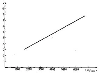
- Remedy: speed control. DPM-20, DPM-25 and DPM-30 DC motors are easiest, since their speed is linear in supply voltage (Fig. 1).
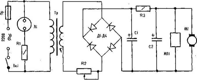
Manual speed control (Fig. 2)
- 1. Switch on (VK1) before the lift and let the speed settle.
- 2. Set a slightly high voltage with R2, so the speed is a little too high.
- 3. Feed liquid under pressure to the shutter; speed and voltage drop.
- 4. Adjust pressure and voltage until the voltmeter shows the required speed, then record.
- Example: dots every 0.01 s need 6000 rpm, which is 8 V on a DPM-20.
- Check the speed with instruments periodically.
- Electronic stabilisation also works. For DPM motors, see Radio, 1978, No. 4, p. 38.
Accuracy
- A recorder on the bar end is affected by bar bending (A. S. Medvedev, A. A. Lukashev, V. B. Kanevsky, 1980).
- Speed control plus an allowance for bending gives more reliable space–time data.